How to Choose Flange Dimensions for a Sintered Bushing
How to Choose Flange Dimensions for a Sintered Bushing
Choosing a flanged sintered bushing is not only about selecting the bore size and outer diameter. In many real assemblies, the flange dimensions are what determine whether the part installs correctly, locates positively, and survives service without creating packaging or wear problems. That is why engineers often discover that the sleeve portion of the bushing was easy to size, but the flange was the part that actually required more thought.
This is especially true in motors, appliances, actuators, compact gear housings, and OEM mechanical assemblies where the flange may do more than simply “sit outside the housing.” In practice, it may help:
- stop the bushing at the correct installation depth
- provide a locating face
- support light axial contact
- stabilize the bearing position
- reduce the need for separate retention features
That is why flanged bushing dimensions are not just drawing details. They are design decisions.
The real engineering question is not “what flange size exists in a catalog?”
The better question is:
What flange dimensions allow this bushing to locate correctly, fit the housing, support the expected assembly logic, and still leave enough room for the rest of the product?
This article explains how to choose flange dimensions for a sintered bushing, what dimensions matter most, what common mistakes to avoid, and how to think more clearly about flange size in practical OEM design.
Why Flange Dimensions Matter So Much
A plain sleeve bushing mainly asks the designer to size:
- bore
- outer diameter
- length
A flanged bushing adds a second layer of geometry:
- flange outer diameter
- flange thickness
- flange seating face
- relationship between flange and housing shoulder
- relationship between flange and nearby rotating or stationary parts
That extra geometry is what makes a flanged bushing useful, but it is also what makes it easy to mis-size.
If the flange is too small, it may not provide enough seating or locating confidence.
If the flange is too large, it may interfere with surrounding parts or waste space.
If it is too thin, it may not give the support or durability the design expects.
If it is too thick, it may create packaging issues or shift the shaft position unnecessarily.
This is why flange sizing should never be treated as an afterthought.
The First Design Question: What Is the Flange Actually Doing?
Before choosing any flange dimension, define the flange function.
In most practical assemblies, the flange is doing one or more of the following:
- providing a positive installation stop
- acting as a locating shoulder
- helping resist axial movement of the bushing
- presenting a face against the housing
- supporting light axial load or contact
- replacing extra retention hardware in compact designs
This matters because the “right” flange dimensions depend on the job of the flange.
For example:
- a flange used mainly as an insertion stop may not need the same thickness as one expected to see repeated axial contact
- a flange used only for seating may not need the same diameter as one expected to distribute load over a larger face area
So the first step is not measuring the flange. The first step is deciding what the flange is there to do.
Start with the Sleeve Dimensions, Then Size the Flange
A common design mistake is to look at the flange first because it is visually prominent in the drawing. In reality, the flange should be sized after the main bearing body has been defined.
The normal logic is:
- define the shaft diameter
- define the bushing bore
- define the outer diameter of the body
- define the body length required for radial support
- then size the flange according to installation and axial needs
This sequence matters because the flange is not an independent feature. It is part of the total bearing geometry.
If the flange is sized without reference to body length, housing thickness, or shaft layout, the part may look acceptable on paper but feel awkward in the actual assembly.
How to Think About Flange Outer Diameter
The flange outer diameter is usually the first flange dimension people notice. But it should not be selected only by visual proportion.
The flange outer diameter should be large enough to:
- provide a stable seating face
- distribute contact load sensibly
- prevent the bushing from being pushed too far into the housing
- match the housing shoulder or support face properly
At the same time, it should not be so large that it:
- interferes with adjacent parts
- wastes installation space
- creates unnecessary package growth
- complicates surrounding housing geometry
In practical terms, flange diameter is usually a balance between:
- support area
- available space
- axial load expectations
- housing-face geometry
The correct flange diameter is therefore usually the smallest diameter that still gives a confident seating and locating function for the intended application.
How to Think About Flange Thickness
Flange thickness is often even more important than flange diameter, because it directly affects:
- how solid the seating face feels
- how much axial contact the flange can tolerate
- how the part installs against the housing
- how much axial stack-up space the bushing consumes
A thicker flange may provide:
- more mechanical confidence
- better support in assembly
- a more robust axial locating face
- improved durability where the flange sees repeated contact
But a thicker flange may also:
- consume valuable axial space
- change shaft positioning in the assembly
- create stack-up issues
- increase the risk of overdesign in compact products
A thinner flange may save space, but it should still be thick enough to perform its locating and support role reliably.
This is why flange thickness should be chosen based on actual function, not just symmetry or appearance.
The Most Important Relationship: Flange vs Housing Face
One of the best ways to choose flange dimensions is to stop thinking of the flange in isolation and start thinking of it as a matched interface with the housing.
The key questions are:
- What surface does the flange sit against?
- How much support does that surface provide?
- Is the housing face flat, stepped, recessed, or shouldered?
- Does the housing distribute load well across the flange?
- Is the flange expected to remain static against the housing, or see axial contact during operation?
This matters because a flange that looks dimensionally fine by itself may still be poorly matched to the housing face.
A flange should generally be dimensioned to work with the real seating surface, not with an imagined idealized one.
When Flange Diameter Should Be Increased
Increasing flange diameter may make sense when:
- the housing face is wide and can support a larger seating area
- axial stability matters more
- the flange needs to distribute contact over more area
- the assembly benefits from a clearer installation stop
- the part must resist being pressed too far into the bore
However, this should still be controlled. A larger flange is not automatically better. It is only better when the design actually benefits from the added face area.
When Flange Thickness Should Be Increased
Increasing flange thickness may make sense when:
- the flange is doing more than simple positioning
- the assembly sees repeated axial contact
- the bushing needs a more robust locating shoulder
- the product is subject to handling, vibration, or installation stress
- the housing geometry supports a thicker flange cleanly
Again, this is not a universal rule. It is an application-specific adjustment.
When Smaller Flanges Make More Sense
A smaller flange may be the better design choice when:
- the assembly is very space-constrained
- the flange is mainly an installation stop, not a significant contact face
- adjacent parts leave little radial room
- the housing already provides strong support
- packaging efficiency matters more than flange oversizing
This is common in small motors, appliance mechanisms, and compact actuators where every millimeter matters.
In those designs, flange dimensions should be large enough to do the job — but no larger.
Why Axial Load Still Needs Honest Review
A common mistake is to assume the flange can take “some thrust,” so exact flange sizing is not very important.
That is too vague.
If the flange is expected to see actual axial contact in service, the designer should review:
- how often that contact occurs
- how much load is involved
- whether the contact is continuous or intermittent
- whether the flange is only locating, or actually bearing load
- whether a separate thrust element would still be better
This is important because flange dimensions that are fine for location only may not be the best for repeated thrust contact.
That does not mean every flanged bushing needs a thrust washer. It means the flange function must be reviewed honestly.
Why Assembly Method Changes the Right Flange Dimensions
Flange sizing also depends on how the bushing is assembled.
If the part is:
- press-fit into a housing
- inserted against a shoulder
- installed in volume production
- replaced during service
- seated manually in a compact mechanism
then flange geometry may need to support:
- easy visual positioning
- repeatable insertion depth
- handling confidence
- reduced installation error
This is why production engineers often care about flange dimensions as much as design engineers do. The flange is part of the assembly method, not only part of the bearing geometry.
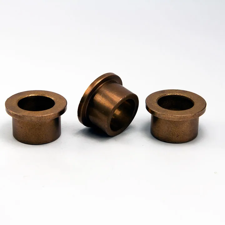
How SINTERED BRONZE BUSHING 25X32X40X5X32 Fits This Topic
A part such as SINTERED BRONZE BUSHING 25X32X40X5X32 is a useful reference example because it shows the full logic of a flanged bushing dimension set:
- 25 = shaft-related bore dimension
- 32 = body outer diameter
- 40 = flange outer diameter
- 5 = flange thickness
- 32 = body length
This is exactly why flange dimension selection matters. The sleeve body and the flange are doing different jobs.
In a configuration like this, the engineer should evaluate:
- whether the 40 mm flange OD is appropriate for the available housing face
- whether the 5 mm flange thickness gives the needed support without using too much axial space
- whether the 32 mm body length gives enough radial bearing support
- whether the total part fits the assembly without overbuilding the design
This is the correct way to think about flanged bushing dimensions: as a coordinated geometry, not a set of unrelated numbers.
Common Buyer and Design Mistakes
Mistake 1: Copying flange proportions from another part without checking the housing
A flange that works in one housing may be wrong in another.
Mistake 2: Oversizing the flange “just in case”
This often wastes space and complicates packaging without improving performance meaningfully.
Mistake 3: Undersizing flange thickness to save space
If the flange becomes too slight for the real assembly role, the design may lose positional confidence.
Mistake 4: Treating the flange only as a stop feature
In some assemblies it is also a functional contact face and should be sized accordingly.
Mistake 5: Ignoring axial stack-up
Flange thickness changes assembly position and must be included in the real dimensional chain.
How to Choose More Reliably
If you are choosing flange dimensions for a sintered bushing, start with these questions:
What is the flange required to do?
Locate, seat, stop, support axial contact, or all of these?
What housing face will support the flange?
This often determines whether the flange is actually properly sized.
How much radial room is available?
This constrains flange outer diameter.
How much axial space is available?
This constrains flange thickness.
Is the flange mainly a locating feature or a bearing face?
The answer usually decides whether a lighter or more robust flange is appropriate.
FAQ
How do I choose flange dimensions for a sintered bushing?
Start by defining the bushing bore, body OD, and body length first, then size the flange according to housing support, axial location needs, and available radial and axial space.
What is the most important flange dimension?
There is no single most important one. Flange outer diameter and flange thickness both matter, but the real priority depends on the housing interface and the flange’s function.
Should the flange be as large as possible?
No. It should be large enough to provide reliable seating and location, but not so large that it creates packaging or assembly problems.
How thick should a flanged bushing flange be?
Thick enough to perform its locating and support role reliably, but not thicker than the assembly needs. The right thickness depends on space, support conditions, and whether the flange sees axial contact.
Does the flange carry load?
It may carry light axial contact or provide seating support, but the actual role must be reviewed honestly in the design.
Can the flange replace a thrust washer?
Sometimes, depending on load and contact conditions. But the flange should not be assumed to replace a thrust washer automatically in every assembly.
Why is housing geometry so important in flange sizing?
Because the flange works against the housing face. If the housing does not support the flange properly, the flange dimensions may be wrong even if the part drawing looks reasonable.
What kind of application suits SINTERED BRONZE BUSHING 25X32X40X5X32?
It suits assemblies where the shaft needs radial support, the bushing benefits from a defined seating face, and the available housing geometry can support the chosen flange diameter and thickness properly.
Conclusion
Choosing flange dimensions for a sintered bushing is not about making the flange look balanced on a drawing. It is about making sure the flange performs the job the assembly actually needs: locating the bearing, seating against the housing, controlling installation depth, and in some cases supporting light axial contact.
The right flange dimensions come from the relationship between the bushing and the housing, not from a generic rule. Flange outer diameter, flange thickness, body length, and housing-face geometry all need to work together as one design.
For technical professionals and OEM customers, the most useful design question is not “what flange size is typical?” The better question is “what flange dimensions make this bearing easier to install, better supported, and more reliable in this actual assembly?” That is the logic that leads to better flanged bushing design.
Engineering Tools for Bushing Selection
If you are evaluating dimensions, fit, or estimated part weight for a sintered bronze bushing project, the following internal tools may be useful during design and quotation review:
Mechanical Design
Calculation Tools